ENGINEERING LAB
ELECTRICAL / PLC / AUTOMATIONLEARN. BUILD. UNDERSTAND.

KoniamiVirtual Lab.

From your first circuit
to the logic that makes it move.
A digital practice space for learning electrical engineering and automation.

Circuit
simulation
PLC &
automation
Wiring
diagnostics

FOR CURIOUS MINDS.
SMK · POLYTECHNICS · UNIVERSITIES · TRAINING CENTERS

FIG. 01 / CONVEYOR STATIONCONCEPT STUDY
SENSORI0.2 / INPUTPNEUMATIC ACTUATORY0.1 / OUTPUTCONVEYOR MOTORQ0.0 / OUTPUT
I0.2 SensorY0.1 ActuatorQ0.0 Motor
ENGINEERING IN MOTIONCircuits, logic,
and system response.
Conceptual animation.
RUNSENSORMOTORSENSORTONT#3s
A PRACTICE SPACE FOR
THE NEXT GENERATION OF ENGINEERS
01—CIRCUITS
Build & understand
02—LOGIC
Program & observe
03—UNDERSTANDING
Trace & fix

THE ENGINEERING MINDSET / 01

More than
switching it on.
Know why.

Build understanding through experiment. Connect components, watch how they behave, then trace the logic behind every response.

01DESIGN THE
CIRCUIT
02PROGRAM THE
PLC LOGIC
03OBSERVE &
TRACE

YOUR WORKBENCH / 02

Pick your first challenge.

Four motor control exercises and six ready-made automation labs. Every module starts from the Lab list in Studio.

MOTOR CONTROL / BASIC

Start with the basics.

Get to know contactors, protection, and self-holding. Wire a start–stop control to see how a motor is controlled.

Open in Studio ↗

In Studio, choose Lab, then pick this module.
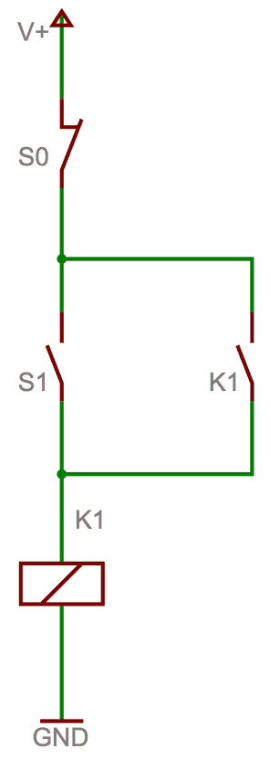
Start–stop control circuit with holding contact K1
Reference diagram: start–stop control (self-holding). Wendelin, CC BY-SA 3.0, cropped.

FOR INSTITUTIONS / 03

A learning space
as wide as curiosity.

Prepare students and trainees before they enter the physical lab. Give them room to try, make mistakes, and understand.

Vocational schools 01 / FUNDAMENTALS
Polytechnics & universities 02 / ENGINEERING
Training centers (BLK & BPVP) 03 / TECHNICAL SKILLS

SIMULATION SCOPE / 04

What the Simulation Models

01

Component connectivity

Wires connect supply, contactors, relays, timers, and motors, and the connections are solved as an electrical circuit.

02

Circuit state propagation

Voltage reaches coils and loads through the wired paths, so components change state because of how you wired them.

03

Contactor behavior

Contactors pick up and drop out with coil voltage, and self-holding (seal-in) paths work as wired.

04

Electrical interlocks

Interlock wiring decides whether two contactors can energize together.

05

Motor control sequences

Timers drive star–delta transitions and sequential motor starts.

WIRING DIAGNOSTICS / 05

How Wiring Is Checked

Diagnostics read the circuit you actually wired. For the supported starter patterns they also compare it with the expected connections.

Supported troubleshooting scenarios

  • Missing connections
  • Swapped phases
  • Missing or ineffective interlock
  • Supply short circuit
  • Invalid connection or coil voltage
  • Contactor that can never energize
Overview Detected pattern, wiring completeness, and interlock compliance.
Guide Step-by-step wiring help, including which wire to remove.
Logic Behavior findings with the path that proves each one.

RIGHT & WRONG / 06

Correct and incorrect wiring

Forward–Reverse

CorrectEach contactor has a normally closed contact of the other in its coil path, so only one can energize.
IncorrectThe interlock contact is missing or only in the seal-in branch, so both contactors can be on and the Logic tab reports a short circuit.

Star–Delta

CorrectStar and delta contactors are interlocked and the timer feeds the transition.
IncorrectStar and delta can close together, or the timer is not connected so delta never energizes.

PRACTICE FLOW / 07

Example Practical Workflows

01

Prepare before the lab

Build a DOL or Star–Delta starter, run it, and read the diagnostics before wiring the physical panel.

02

Troubleshooting drill

Remove an interlock or swap two phases, then use the Logic findings and the wiring guide to find and fix the fault.

03

First look at automation

Open the Level ON/OFF lab, watch the PLC cycle the pump, then move the switching levels and compare with the PID lab.

SCOPE & LIMITS / 08

Technical Scope and Limitations

  • Complements physical laboratory practice; it does not replace it.
  • Represents supported electrical circuit behaviors only. Dahlander two-speed starters are still in development.
  • Physical phenomena are simplified for learning.
  • Not a substitute for certified engineering verification or commissioning checks.
  • Pattern-based guidance covers the supported starter patterns; other circuits may receive less detailed results.

Institution features (planned)

These are plans, not features that are available or promised today.

  • Institution workspace
  • Instructor and learner management
  • Class management
  • Practical assignments
  • Simulation result submission
  • Wiring assessment
  • Learning progress analytics
  • Exportable reports

INSTITUTIONAL DEMO / 09

See How Koniami Can Support Practical Learning at Your Institution

  • 01 — Tell us about your institution and practical learning needs through this form.
  • 02 — Our team contacts you by work email to schedule a demo.
  • 03 — We discuss the relevant simulation modules and the possibility of a pilot program.

QUESTIONS / 10

Frequently asked questions.

Which simulation modules are available?

Four motor control exercises (DOL, Star–Delta, Forward–Reverse, Sequential) and six ready-made automation labs (VFD manual speed, heavy start and protection, level ON/OFF, motor speed PI, PLC motion control, PID level). Dahlander is still in development.

How does wiring validation work?

Diagnostics read the circuit you wired, detect the supported starter pattern, compare it with the expected connections, check interlocks, and run behavior checks that show what can or cannot happen.

What about circuits outside the supported patterns?

You can still wire supported components and run the simulation. Pattern-based completeness and wiring guidance cover the supported starter patterns, so other circuits may receive less detailed results.

How accurate is the simulation?

It represents supported electrical behaviors and simplifies physical phenomena for learning. It is not a substitute for certified engineering verification or physical commissioning checks.

Do I need to install anything?

No. Virtual Lab runs in modern browsers.

Do I need an account to use it?

Studio asks you to sign in when you create a lab. A free account is enough to try Virtual Lab.

Does Virtual Lab replace the physical laboratory?

No. It helps learners practice and understand circuits before working with real equipment. Hands-on practice is still needed.

How can an institution request a demo or pilot?

Fill in the demo request form on this page. Our team contacts you at the work email you provide and can discuss pilot options with you.

A NOTE FROM THE LAB

Digital experiments.
Real understanding.

Virtual Lab supports learning. Practice on physical equipment, safety procedures, and instructor guidance remain essential to engineering education.